

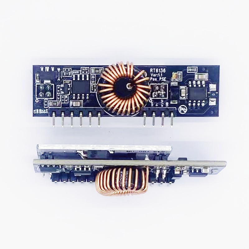
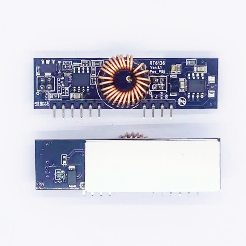
RT6136
This document contains proprietary information of ring&tone and is not to be disclosed or used without the prior written permission of ring&tone.
Due to update and improvement of ring&tone products and technologies, information in this document is subjected to change without notice.


RT6136_ 12V_Pse Module_SPEC_V1_0Features:
- Small package
- Compliant with IEEE802.3 at & af
- Low cost
- Output power up to 30W
- Minimal (low cost) external
- components required
- Over-current and short circuitprotection
- Available in Industrial Temperatureversion.
- Internal integrated boost conversion circuit, matching POE output
Applications:
- PoE power supply system
Description:
The RT6136 is a single channel Power Sourcing Equipment (PSE) module designed for
use in Power over Ethernet (PoE) applications for a wide range of power levels from 15.4W (IEEE802.3af) up to 30W (IEEE802.3At) proprietary power levels.
The RT6136 is capable of delivering up 30W ,The RT6136 is aimed at applications requiring PSE functionality such as CCTV DVR, home networking and industrial ethernet.
RT6136 is a self-contained module, requiring just a few external components to provide a
great deal of control and feedback over each Powered Device (PD) that is connected to
the PSE.
- RT6136 Product Selector
|
Part Number† |
Output Power (W) |
|
|
RT6136-AT |
|
0W-30w |
- Signature and Classification
The RT6136 will automatically perform the Signature and Classification, the timing sequence for a Type 1 Powered Device (PD) and the timing sequence for a Type 2 PD.
In the ‘IEEE802.3bt’ classification the first pulse is much longer. This is to indicate to the PD that implements the bt specification’s lower Maintain Power Signature (MPS) requirements (see section 5.6 below for details of MPS). Additionally if is set in ‘BT 1 pair’ or ‘BT Type 3’ modes the will produce a third class pulse looking for a change in class current presented. If the current changes correctly will produce 1 further pulse which indicates to the PD the requested power (>30W) has been granted. After classification is complete the will begin to power up its output with the current limit selected based on the detected class and mode of the module.
- 1 Signature Detection
To ensure that the RT6136 does not apply power to a non PoE enabled device the Port output first checks for a valid PoE signature. The PD should present a nominal 25kΩ (23.75kΩ to 26.25kΩ) Signature resistance; if the RT6136 does not see a valid signature then it will disconnect, wait approximately 2 seconds then try again, see Figure 7 below.
- 2 Classification
On completion of a valid signature, the RT6136 will then interrogate the PD to see if a classification signature is present. The classification signature is used to determine the amount of power the PD will draw and limits the output power accordingly (see Table 2). It is optional for the PD to present a classification signature and the RT6136 will default to Class 0 if the PD does not present one.
Table shows the measured current limits that the RT6136 uses to assign a classification value.
|
Measured Current |
Classification |
|
0mA to 6.5mA |
Class 0 |
|
>6.5mA to 14.5mA |
Class 1 |
|
>14.5mA to 23mA |
Class 2 |
|
>23mA to 33mA |
Class 3 |
|
>33mA to 48mA |
Class 4 |
- Input Protection
The RT6136 has built-in Tranzorb diode across its input, to protect the module from transients from the power supply.
- 3 Maintain Power Signature
On successful completion of a valid signature (and classification) the RT6136 will apply main power to the Port output..
Once main power has been applied, the RT6136 with constantly monitor the PD to ensure that it is still connected; this is referred to as the Maintain Power Signature (MPS).
The RT6136 uses the dc detection method of MPS and will remove power if the current drawn falls below the detect threshold. If the RT6136 Port output current is ≥10mA the output will remain on. If the Port output current is ≤ 5mA the output will be turned off and the RT6136 will return to the signature cycle (looking for a valid signature).
- Output Current Limits
The RT6136 has two over current limits - Current Limit 1* and Current Limit 2*.
The RT6136 will allow the Port output to exceed Current Limit 1 (but not Current Limit 2) for a short duration – TLIM1*. If the Port output continues to exceed Current Limit 1; the output power will be removed
If the output exceeds Current Limit 2, the RT6136 will remove power (without waiting for TLIM)
- Output Power
The RT6136 is capable of delivering up to 30W, when supplied with its maximum input voltage of 57V.
Please note this is not the power available at the input of the Powered Device (PD). There are cable, connector and polarity protection losses to be taking into account.
- Output Short-Circuit Protection
In addition to the over-current protection the RT6136 has built-in output short-circuit protection.
If the Port output is shorted, the RT6136 will limit the current and remove the power
- 1 Absolute Maximum Ratings1
|
|
Parameter |
Symbol |
Min |
Max |
Units |
|
1 |
DC Supply Voltage |
VDD |
-0.3 |
60 |
V |
|
2 |
Storage Temperature |
TS |
-40 |
+100 |
OC |
Note 1: Exceeding the above ratings may cause permanent damage to the product. Functional operation under these conditions is not implied. Maximum ratings assume free airflow.
- Recommended Operating Conditions
|
|
Parameter |
Symbol |
Min |
Typ |
Max |
Units |
|
|
|
|
|
|
|
|
|
|
|
VDD (Type1) |
10 |
|
36 |
V |
|
1 |
Input Supply Voltage |
VDD (Type2) |
|
|
|
V |
|
|
|
VDD (Type3) |
|
|
|
V |
|
2 |
Standard Operating Temperature - |
TOP |
-20 |
25 |
70 |
Ta / OC |
|
|
|
|
|
|
|
|
- Pin Description:
|
Pin # |
Name |
Description |
|
1 |
CTL |
Pulled low to turn off the module, usually floating |
|
2 |
0V |
0V. This pin is the return path for the isolated VIN+ power supply. |
|
3 |
0V |
|
|
4 |
VIN+ |
Main Power Supply. This pin connects to an isolated 10V to 36V supply; relative to the 0V. |
|
5 |
VIN+ |
|
|
6 |
52V_out |
Internal 52v power output, connected to filter capacitor. |
|
|
|
|
|
7 |
52V_in |
52v power input,power for Internal pse ic . |
|
8 |
Port- |
Port Output Return. This pin is the return path for 52V_out |
|
9 |
Raf/at |
Connected GND for AF, floating for AT setting |
|
10 |
0V |
0V. This pin is the return path for the isolated VIN+ power supply. |
- RT6136Poe at/af pse Connection 100M Internet:

- RT6136Poe at/af pse Connection 1000M Internet:

- Input Power Supplies
The RT6136 only requires one power supply; to conform to the IEEE802.3 at af specification, this supply must be isolated from mains ground
- Reliability MTBF:
About the life time ,we design according to the following:
- life time of RT6136 : 100,000 hours @ 25°C
- Mechanical / Environmental Performance data
|
Mechanical / Environmental Performance data |
||
|
|
Item |
Requirement and Standard |
|
1 |
Resistance to Wave Soldering Heat |
max Preheat Temp range & time 120 ℃ / 180S max soldering temp &time:265 ℃ / 4S |
|
2 |
Solder ability |
Solder able area shall have minimum of 95% solder coverage. And then into solder bath,Temperature at 245 ±5 ℃ , for 4-5sec. |
|
3 |
Hand Soldering Temperature Resistance |
T > =350 ℃ , 3sec at least. |
|
4 |
Thermal Shock |
subject to follow condition for 5 cycles.1 cycles: -55 ℃ , 30 minutes +85 ℃ , 30 minutes |
|
5 |
Humidity(Temp Cycling) |
less than 95% (non-condensing) ( -20 to 70 ℃) |
|
6 |
Temperature Life |
temperature life at 85℃ for 96 hours. |
|
7 |
Salt Spray |
connectors to 5% salt-solution concentration, 35 ℃ Gold flash for 8 hours there will be no change in the gold layer |
- RT6136 PackageSize: (mm )

- Packaging type & Quantity
EPE or BLASTIC Packaging,
50pcs/ dish
500pcs/box Box size 30*35*20cm 4KG/box