

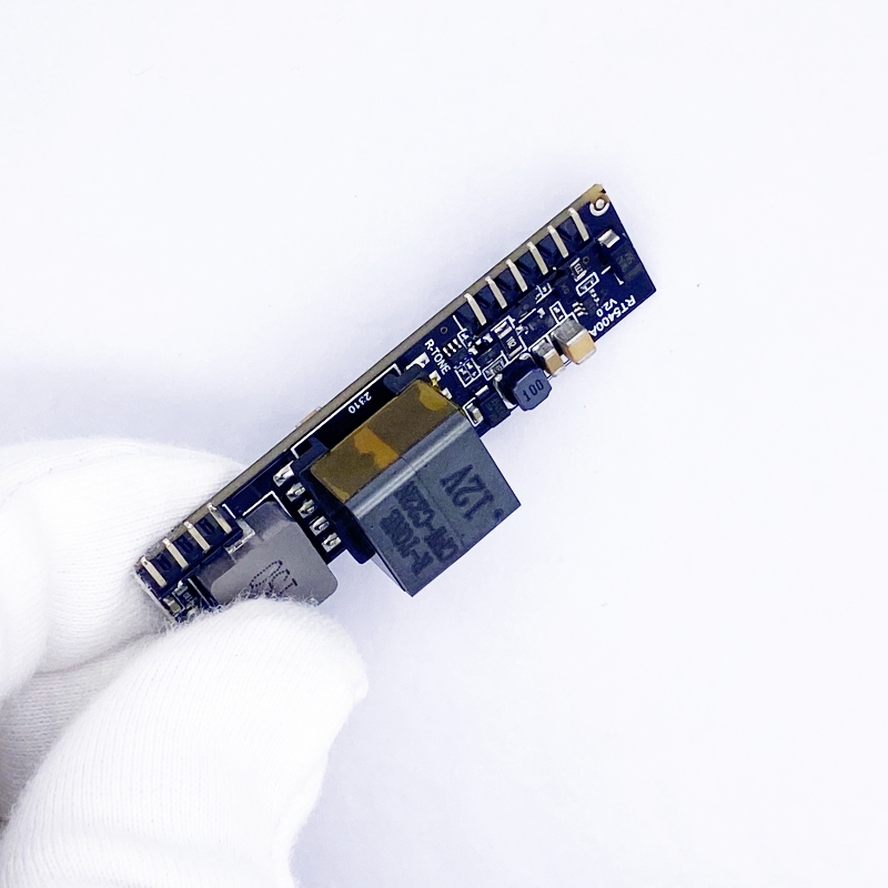

RT5400A
-
The RT5400A series of modules are designed to extract power from a conventional
twisted pair Category 5 Ethernet cable, conforming to the IEEE 802.3af and IEEE 802.3at Power-over-Ethernet(PoE) standard.
The RT5400A signature and control circuit provides the PoE compatibility signature and
power classification required by the Power Sourcing Equipment (PSE) before applying up
to 30W power to the port.
The DC/DC converter operates over a wide input voltage range and provides a regulated
output. The DC/DC converter also has built-in short-circuit output protection.
Related products
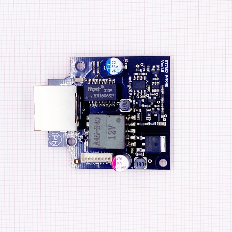
RT30D04A
High Efficiency
30W POE PD Module ( Isolation Model)
Product Description
|
Version |
Date |
Author |
Approved By |
Remarks |
|
V2.0 |
2023/7/1 |
LI xiao yan |
Rock |
|
|
|
|
|
|
|
|
|
|
|
|
|
© 2023 Shenzhen Ring&tone Electronic Technology Co., Ltd. All rights reserved.
This document contains proprietary information of ring&tone and is not to be disclosed or used without the prior written permission of ring&tone.
Due to update and improvement of ring&tone products and technologies, information in this document is subjected to change without notice.
Features:
- IEEE802.3at and IEEE802.3af compliant
- Maximum 30W output power
- Input voltage range 36V to 57V
- Integral high efficiency DC/DC converter.
- Low output ripple and noise
- High performance with low price
- Short-circuit protection
- Transformer isolation ,1500V isolation (input to output)
- Easy to use, with a minimum number of external components.
Applications:
- IP Cameras
- Wireless access point
- Security and alarm systems
- VOIP telephone
- Point of sale network terminal equipment
Description:
The RT30D04A series of modules are designed to extract power from a conventional
twisted pair Category 5 Ethernet cable, conforming to the IEEE 802.3af and IEEE 802.3at Power-over-Ethernet(PoE) standard.
The RT5400A signature and control circuit provides the PoE compatibility signature and
power classification required by the Power Sourcing Equipment (PSE) before applying up
to 30W power to the port.
The DC/DC converter operates over a wide input voltage range and provides a regulated
output. The DC/DC converter also has built-in short-circuit output protection.
- Product Selector
|
Part Number |
Output * |
Maximum Output Power* |
AT-DET LED |
Integrated bridge |
Power structure |
Marking |
Package |
|
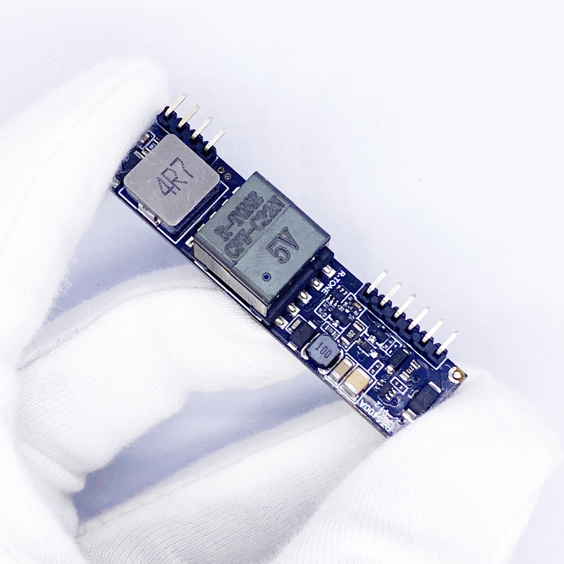
RT5400A-5V |
5V |
25W Peak 30W |
YES |
NO |
Forward |
5V |
DIP |
|
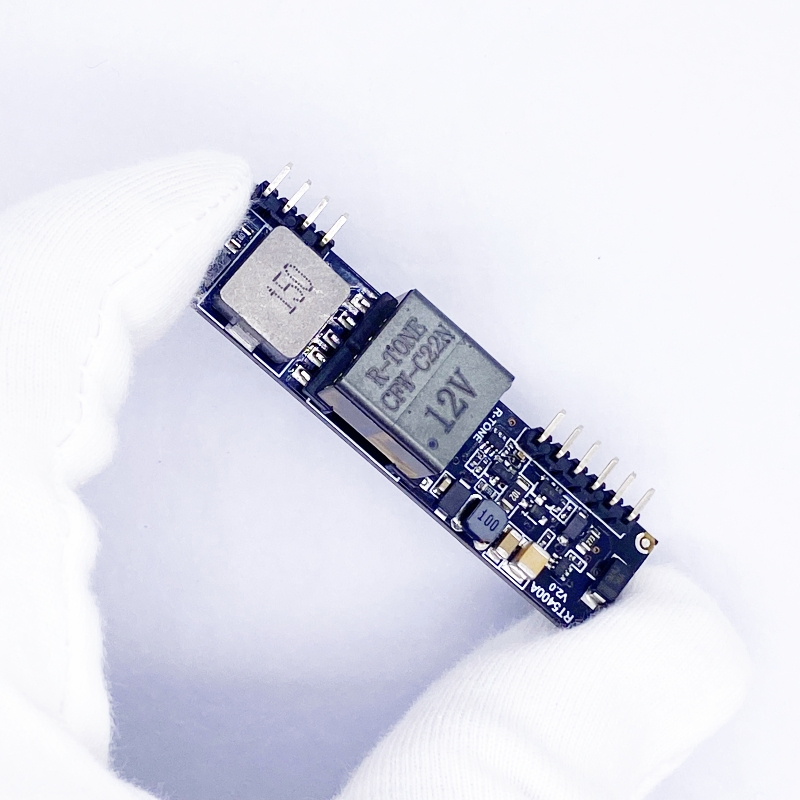
RT5400A-12V |
12V |
30W |
YES |
NO |
Forward |
12V |
DIP |
|
RT5400A-24V |
24V |
30W |
YES |
NO |
Forward |
24V |
DIP |
*At 25°C with VIN = 54V
- RT5400A Pin Description:
|
Pin # |
Name |
Description |
|
1 |
VIN+ |
POE Direct Input +. This pin connects to the positive (+) output of the POE input bridge rectifiers. |
|
2 |
VIN- |
POE Direct Input -. This pin connects to the negative (-) output of the POE input bridge rectifiers. |
|
3 |
AT-DET- |
AT Detect Output. This pin indicates if an IEEE802.3at PSE is supplying power to the RT5400A. |
|
4 |
CAP- |
Internal cap-, need Match Dynamic load ,connecting external cap- ,47uf 100v OR NC |
|
5 |
NC |
not connected |
|
6 |
NC |
not connected |
|
7 |
-VDC |
DC Return. This pin is the return path for the +VDC output. |
|
8 |
+VDC |
DC Output. This pin provides the regulated output from the DC/DC converter. |
|
9 |
ADJ |
Output Adjust. The output voltage can be adjusted from is nominal value, by connecting an external resistor from this pin to either the +VDC pin or the -VDC pin. |
|
10 |
-VDC |
DC Return. This pin is the return path for the +VDC output. |
- Absolute Maximum Ratings
|
|
Parameter |
Symbol |
Min |
Max |
Units |
|
1 |
DC Supply Voltage |
VCC |
-0.3 |
60 |
V |
|
2 |
DC Supply Voltage Surge for 1ms |
VSURGE |
-0.6 |
80 |
V |
|
3 |
Storage Temperature |
TS |
-40 |
100 |
OC |
Note 1: Exceeding the above ratings may cause permanent damage to the product. Functional operation under these conditions is not implied. Maximum ratings assume free airflow.
- Recommended Operating Conditions
|
|
Parameter |
Symbol |
Min |
Typ |
Max |
Units |
|
1 |
Input Supply Voltage1 |
VIN |
36 |
48 |
57 |
V |
|
2 |
Under Voltage Lockout |
VLOCK |
30 |
|
36 |
V |
|
3 |
Operating Temperature2 |
TOP |
-20 |
25 |
70 |
Ta / OC |
|
4 |
Operating Temperature 30W Continuous 24W Continuous |
TOP |
-40 -40 |
25 25 |
70 85 |
Ta / °C |
Note 1: With minimum load
2: See Section Operating Temperature Range
** Extended use close to, or at the maximum operating temperature can reduce the life time of the device.
- Operating temp profile

- DC Electrical Characteristics
|
|
DC Characteristic |
Sym |
Min |
Typ1 |
Max |
Units |
Test Comments |
|
1 |
Nominal Output Voltage |
+VDC |
11.5 |
12.0 |
12.5 |
V |
12V |
|
|
Nominal Output Voltage |
+VDC |
4.75 |
5.0 |
5.25 |
V |
5V |
|
2 |
Line Regulation |
VLINE |
|
0.1 |
|
% |
@ 50% Load |
|
3 |
Load Regulation |
VLOAD |
|
1 |
|
% |
@ VIN=48V |
|
4 |
Output Ripple and Noise 2 |
VRN |
|
180 |
|
mVp-p |
@ Max load2 |
|
5 |
Minimum Load 3 |
RLOAD |
200 200 100 |
|
|
mA |
@ 5V out @ 12V out @ 24V out |
|
6 |
Short-Circuit Duration |
TSC |
|
|
∞ |
sec |
|
|
7 |
Efficiency 5V out |
EFF |
|
91 |
|
% |
|
|
|
Efficiency 12V out |
EFF |
|
93 |
|
% |
|
|
|
Efficiency 24V out |
EFF |
|
92 |
|
% |
|
|
8 |
Isolation Voltage (I/O) |
VISO |
|
1500 |
|
VPK |
Impulse Test |
|
9 |
Temperature Coefficient |
TC |
|
0.02 |
|
% |
Per OC |
Note1: Typical figures are at 25°C with a nominal 52V supply and are for design aid only. Not Guaranteed
2: The output ripple and noise can be reduced with an external filter, see application note.
3: The module can emit an audible noise if operated at less than the specified minimum load and may cause the PSE to fail its MPS .
- Power Classification
The RT5400A classification is fixed at Class 4, this means that an IEEE802.3at Type 1 or an IEEE802.3af PSE will default to Class 0. However an IEEE802.3at PSE will recognise the Class 4 as a Type 2 PD.
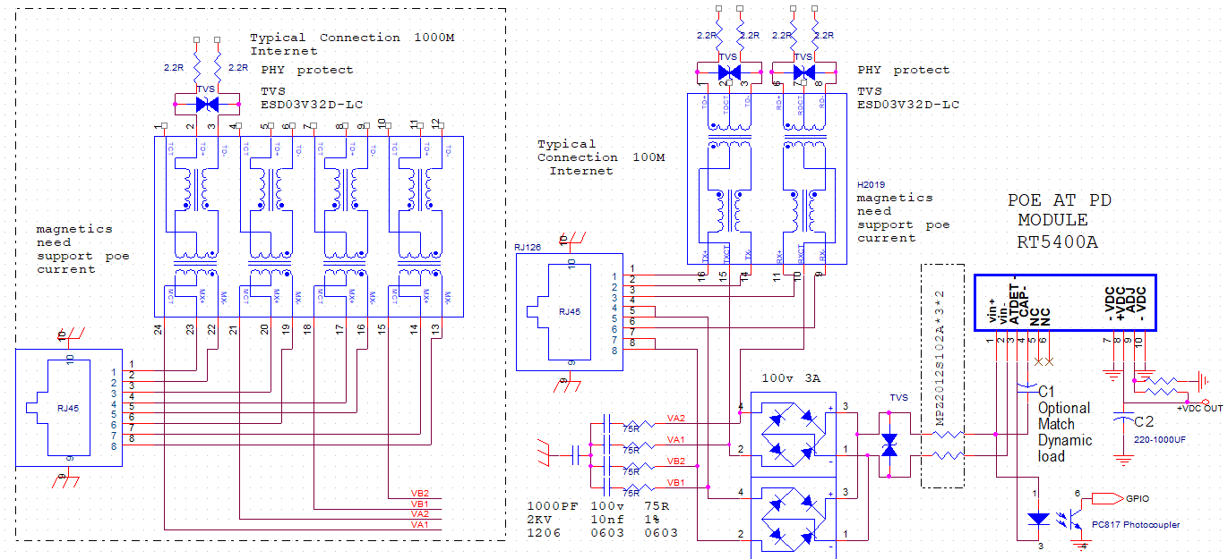
- RT5400A Typical Connection Diagram :
- Output Adjustment
-
Reducing the output voltage, connect R2 between ADJ and +VDC
R2 Value
output voltage
R2 Value
output voltage
RT5400A-5V
open
5V
68K
4.7V
RT5400A-12V
open
12V
68K
10.8V
RT5400A-24V
open
24V
68K
21.6V
Increasing the output voltage, connect R1 between ADJ and -VDC
R1 Value
output voltage
R1 Value
output voltage
RT5400A-5V
open
5V
0R
5.8V
RT5400A-12V
open
12V
0R
12.8V
RT5400A-24V
open
24V
0R
24.8V
*Note: It is important that the minimum output adjust is not taken below 10.8V (12V Nominal) and 21.6V (24V Nominal). Setting the output voltage below this level may result in the module being permanently damaged.
- RT5400A Package Size 6+4PIN : (mm±3mm )


