KS0835F
This document contains proprietary information of ring&tone and is not to be disclosed or used without the prior written permission of ring&tone.
Due to update and improvement of ring&tone products and technologies, information in this document is subjected to change without notice.
Related products


Features:
- Single supply voltagering slic: +3.3V to +5.0V
- Integral high efficiency DC/DC converter.
- Highly integrated withringing generator.
- Tip/Ring polarity reversal.
- 2 / 4 wire conversion
- Constant current feed
- High performance with low price
- Excellent sound quality
- On-Hook Transmission for caller line ID.
- Designed for GSM network
- Easy to use, with a minimum number of external components.
Applications:
- Fixed Cellular Terminals (FCT) applications.
- POS MODEM applications
- Internet Telephony (VoIP) applications.
- Fixed Wireless Terminals (FWT) applications.
- DVB Terminals applications.
- Wireless local loop (WLL)applications.
- GSM gateway
Index:
- unbalanced to ground60dB(300Hz-3400Hz)
- Two-Wire Impedance600R
- Four-wire return loss>24Db
- weighted noise -75dB
- Ringing voltage130VP-P
- Constant current 23-31mA
- Supply Voltage3.2V-5.5VDC
Description:
- The R-TONE KS0835F is a single Subscriber Line Interface Circuit (SLIC).
- The combination of features and packaging offers extremely efficient use of board area, saving significant system size and cost, minimising time to market for Telephony Systems developers.
- The KS0835F has been designed to work with loop lengths of typically 1.0km
- The KS0835F has integral dc/dc converter and ringing generation thus providing all the line powering requirements from a single supply.24V(off-hook)and 48V(on-hook)and 75V(ringing).
- The KS0835F requires a minimum of external components, making it ideal for low line count, short loop length applications, such as WLL Terminal (WLL), Fixed Cellular Terminals (FCT), Fixed Wireless Terminals (FWT) and Internet Telephony (VoIP).
- The KS0835F has an integral DC/DC converter, which generates the battery voltage in the device. This means that only a single supply of between +3.3V to +5.0V is needed, unlike conventional SLICs which will also need a battery voltage of anything between 20V and60V ( 75V for ringing). This confers a significant cost, space and time to market benefit on the equipment designer.
Absolute Maximum Ratings:
|
|
Parameter |
Symbol |
Min |
Max |
Units |
|
1 |
DC Supply Voltage |
VCC |
-0.3 |
5.5 |
V |
|
2 |
Maximum Power Dissipation, Off Hook @ 25oC |
PSLIC |
|
1.2 |
W |
|
3 |
Operating Temperature |
TOP |
0 |
70 |
OC |
|
4 |
Storage Temperature |
TS |
-40 |
+100 |
OC |
DC Electrical Characteristics*
|
Characteristic |
Sym |
Min |
Typ |
Max |
Units |
Test Comments |
|
Supply Current |
ICC |
|
40 50 |
|
mA
|
5V (on-hook) 3.3V(on-hook) |
|
|
270 320 |
|
mA |
5V (off-hook) 3.3V(off-hook) during ring |
||
|
|
180 220 |
|
mA |
5V (during ring) 3.3V(during ring) |
||
|
|
|
|
|
|
||
|
Constant current |
Ibat |
21 |
23 |
35 |
mA |
|
|
Power Dissipation |
Pd |
|
30/850
|
|
mW
|
On/off hook (during 23mA Constant current) |
|
Ringing voltage |
Ving |
|
130 |
|
VP-P |
|
|
off-hook voltage |
Vab |
|
48 |
|
V |
|
|
Supply current in power down |
IPD |
|
7 5 |
|
mA mA |
@ 5.0V @ 3.3V |
All DC Electrical Characteristics are over the Recommended Operating Conditions with VCC at +5.0V +1%,or +3.3V +1%, unless
otherwise stated.
2) Operating currents are dependent on the users application.
*Typical figures are at 25°C and are for design aid only. Not Guaranteed
AC Electrical Characteristics*
|
Characteristic |
Sym |
Min |
Typ |
Max |
Units |
Test Comments |
|
Two- Wire Impedance |
Z0 |
|
600 |
|
Ω |
|
|
Absolute Voltage Gain |
T,R-VX VR-T,R |
-6 -6 |
0 0 |
6 6 |
dB |
|
|
Relative Gain. Referenced to 1kHz |
Gf |
-0.5 |
|
+0.5 |
dB |
Over frequency range 300 to 3400 Hz |
|
Two-wire return loss |
RL |
30 |
|
|
dB |
300-3400HZ,600R load |
|
Four-wire return loss |
THL |
30 |
|
|
dB |
300-3400HZ, 600R load |
|
unbalanced to ground |
|
60 |
|
|
dB |
300-3400HZ,off-hook |
|
common-mode rejection ratio |
CMRR |
45 |
55 |
|
dB |
|
|
weighted noise |
|
-75 |
|
|
dB |
|
|
total harmonic distortion |
THD |
70 |
|
|
dB |
300-3400HZ,off-hook |
This applies to 3 phones with tone ringers or 2 phones with mechanical bells.
*Typical figures are at 25°C and are for design aid only.
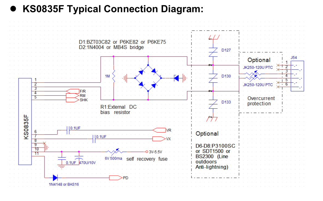
Pin Description:
|
Pin # |
Name |
Description |
|
1 |
RING |
Ring. Connects to the subscriber line Ring. |
|
2 |
TIP |
Tip. Connects to the subscriber line Tip. |
|
3 |
F/R,25Hz |
Forward/Reverse. A logic (H) will reverse the Tip and Ring voltage polarities. F/R is toggled to produce the ringing output. Logic (L) for other modes.
|
|
4 |
RM |
Ringing Mode. Sets bias conditions during ringing. Must be set to logic (H) during ringing. Logic (L) for other modes. |
|
5 |
SHK |
Switch Hook. Indicates an off-hook condition when at logic (H). |
|
6 |
VR |
Audio In Negative. Analog input signal from the Codec (which is output on Tip and Ring). |
|
7 |
VX |
Audio Out. This is the analog output signal (from Tip and Ring) to the Codec. |
|
8 |
NC |
No Connection. Do not connect to this pin. |
|
9 |
GND |
DC/DC Ground. Ground input for the DC/DC converter. |
|
10 |
+VDC |
DC/DC Supply. +5.0V or +3.3V input for the DC/DC converter. |
|
11 |
PD |
Power Down DC/DC Converter. A logic (L) on this pin powers down the module. DO NOT put logic (H) on this pin. |
1 Ringing
The ringing signal is generated by switching the SLIC into ringing mode, by setting the RM pin high, and then toggling the F/R pin at the required frequency and cadence. The toggling of the F/R pin produces a balanced signal at Tip and Ring.
During ringing the integral DC/DC converter is switched produce a battery voltage of 75V.The slope of the edges on the ringing waveform is set internally to give the correct waveform with 20Hz to 25Hz ringing frequency.
2 Tip & Ring Polarity Reversal
If F/R is held at logic (H) (Forward) the d.c. voltage at Ring is negative with respect to Tip. If F/R is taken to logic (L) (Reverse) the voltage at Ring is positive with respect to Tip.
3 Switch Hook Detection
When an “off-hook” condition occurs during ringing, the ring-trip circuit on the KS0835F senses the loop current flowing and signals the off-hook condition on the SHK output. The SHK signal must be “de-bounced” (by the controlling processor) for 10ms to remove any spurious pulses. 。
KS0835FProduct Selector
|
Marking |
Supply Voltage (V) |
Constant current feed to line (mA) |
Gain 2 Wire to VOUT |
Gain VIN to 2Wire |
Ringing voltage (Vp-p) |
Supply Current, on-hook (mA) |
Supply current, off-hook (mA) |
Ringing Load (REN) |
Package |
|
KS0835F |
3.2~5.5 |
23~31 |
0dB |
0dB |
120~135 |
50-35 |
310-270 |
3 |
SIL |
|
|
|
|
|
|
|
|
|
|
|
|
|
|
|
|
|
|
|
|
|
|
|
|
|
|
|
|
|
|
|
|
|
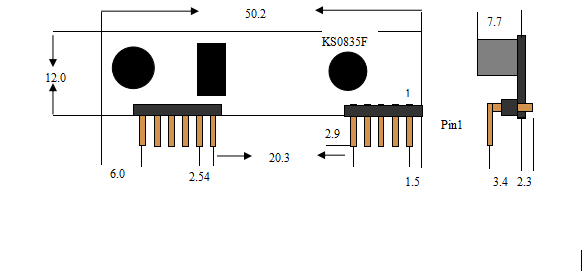
PackageSize: (mm ±3mm )
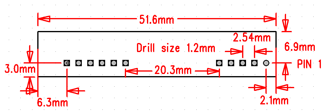
PCB Decal : (mm ±3mm )